Search Microphones
Share This Page
| Tweet |
Related Microphones


 with the U-47.")


Mods for the M 49
- The Mic Shop

Bill Bradley restores vintage mics in Nashville, TN. - Hamptone

Scott Hampton repairs vintage tube mics, especially those needing new power supplies. His mic repairs involve replacing and updating selected components, fine-tuning the circuitry, and restoration of the mic's original sonic character. He can also furnish a Hamptone second-generation Tube Mic Power Supply.

Pricing & Availability
- MSRP: n/a
- Discontinued
Tags
Reviews & News
M 49 Documentation
 Neumann M 49
Multi-Pattern Tube Condenser Microphone
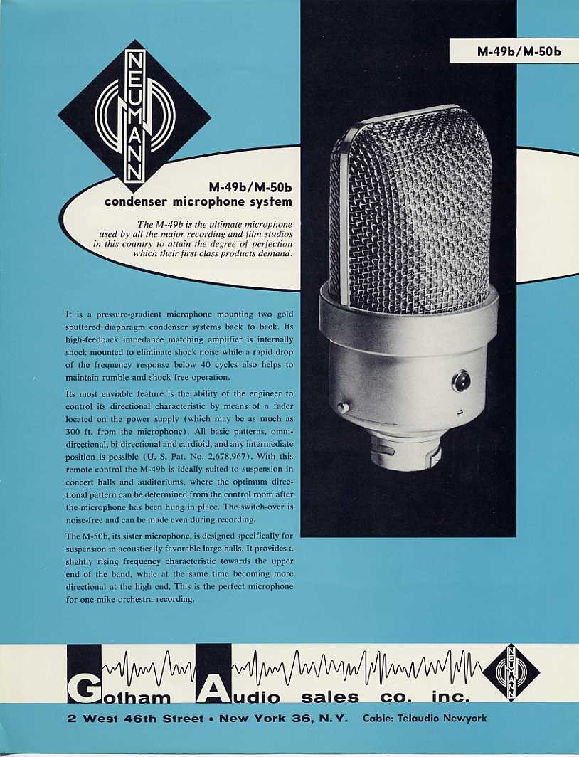
The M 49 was a multipattern large-diaphragm tube microphone with an important new innovation: the mic’s pickup pattern could be adjusted remotely, by a dial on the power supply.
Another new innovation was that the mic maintained nearly equal sensitivity and output level across patterns — unlike the U-47, for example, which was 5dB hotter in Cardioid than Omni.
 Maintaining output level required a change in the polarization voltage circuitry. Whereas the U-47’s circuit would disconnect the capsule’s rear diaphragm in Cardioid mode, in the M 49 both diaphragms were always polarized — the front at a constant 60Vdc, and the rear from 0Vdc to 120Vdc. When set to Cardioid, the rear diaphragm polarization voltage was 0Vdc.
Martin Schneider
To my knowledge, the M49s were mostly used not at ‘zero volts’ but at a ‘best cardioid’ setting. Some users even made marks on the potentiometer [to indicate the] ‘best cardioid’ setting.
(According to Martin Schneider, The M149’s Cardioid setting does not set the capsule’s rear diaphragm to 0Vdc, but rather to a small positive voltage, in order to widen the K47/K49 capsule’s native supercardioid-ish response with a small amount of the rear diaphragm’s in-phase signal.)
The remote-control potentiometer system was developed by Herbert Großkopf of NWDR (Nordwestdeutscher Rundfunk). According to Neumann historian Anselm Roessler, Neumann acquired the rights to this invention for use in the M 49.
Stephen Paul
The 49 had several other interesting features, including one of the first attempts to limit the effect of grille resonance on the response. Because the grille is slanted and presents a continuously varying profile to the capsule, there are fewer standing waves generated.
These new features made the M 49 significantly more versatile than its predecessors and competitors, and it enjoyed rapid success in the broadcast and recording markets.
 Like its omnidirectional sibling, the M 50, the M 49 was initially released with a Hiller MSC2 tube, soon replaced by the Telefunken AC701 subminiature triode.
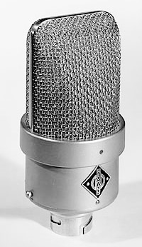
The two mics are nearly identical in appearance; the primary distinguishing cosmetic feature is the color of the “jewel” above the Neumann badge. On the M 49, the jewel is red.
Output impedance was wired at 200 Ohms from the factory. The product manual advised that “by changing two links on the output transformer, the amplifiers can be easily changed to 50 Ohms whereby the output voltage falls by 6dB.”
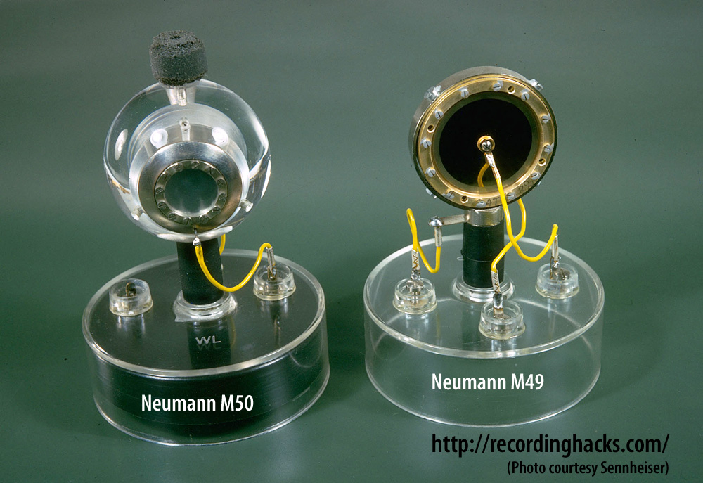 The capsule in the original version of the M 49 was Neumann’s PVC-diaphragm M7. This was subsequently replaced (as in the U47) with the Mylar-diaphragmmed K49. (The K49 was K47 capsule, identical in every respect but the name.)
Production M 49 microphones incorporated the following major component changes:
- 1951 - Hiller MSC2 tube, M7 capsule
- 1954 - MSC2 replaced by Telefunken AC701
- 1956 - M7 replaced by K49 capsule
- 1958 - the M49b incorporated a new “BV11” transformer and some circuit-value changes, according to Klaus Heyne.
- 1961 - for the broadcast market, the M49 was fitted with a 7-pin Tuchel connector and redesignated M 249.
Klaus Heyne
All M49 models after 1957 had a “cardioid only” switch built in, to achieve a 4dB s/n improvement [as compared to setting the pattern] remotely, from the power supply.
The M 49 was discontinued in 1974.
M49 capsule/circuitry photo credit: Oliver Archut
The Neumann M 49 is also known as: M49, B-M49.
The mic was released in 1951.
Specifications
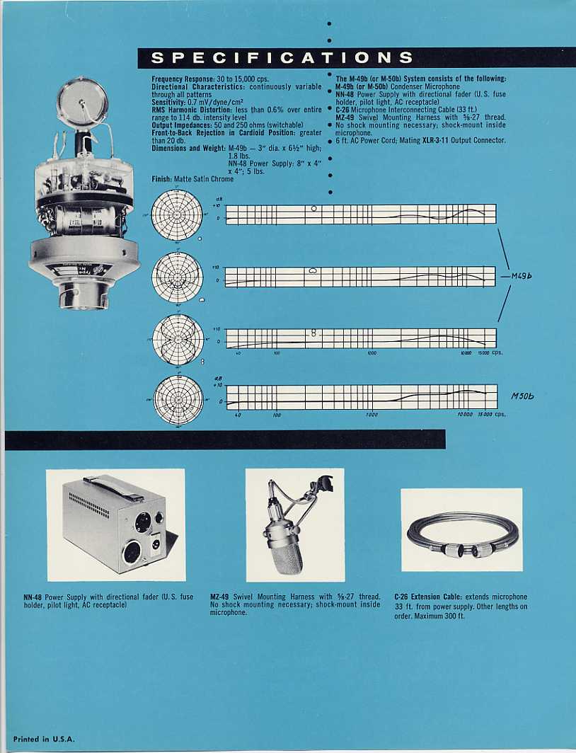
| Frequency Response - OmnidirectionalClick Graph to Compare! |
|---|
 |
| Frequency Response - CardioidClick Graph to Compare! |
 |
| Frequency Response - BidirectionalClick Graph to Compare! |
 |
| Pickup Patterns | Pads & Filters |
|---|---|
|
Omnidirectional
(n/a mV/Pa; 40 - 16,000 Hz) Cardioid (n/a mV/Pa; 40 - 16,000 Hz) Bidirectional (n/a mV/Pa; 40 - 16,000 Hz) |
|
| Capsule Dimensions | Impedance | SPL/Noise |
|---|---|---|
| Diameter n/a |
200 Ohms (Low) | Max SPL: 125 dB |
| Weight | Length | Max Diameter | Interface(s) |
|---|---|---|---|
| 800g (28.22oz) | 163mm (6.42'') | 80mm (3.15'') |
|
| Power Specifications |
|---|
|
Did we get anything wrong on this page? Please let us know!