
Cheap tube mic upgrade case study
Sunday, July 31st, 2022 | by matthew mcglynn
A MicParts customer recently sent us two Carvin CTM-100 tube mics with a request that we upgrade the circuits and capsules, and match the two mics. We documented the process, and measured the mic’s electronic and acoustic performance before and after, to illustrate the value of the upgrade process.
Read on for an inside look at some of the, shall we say, non-optimal behaviors of the stock microphones, and an analysis of the mic after we replace 100% of the signal path.
Overview of the stock microphone
The CTM-100 is a rebranded Alctron T11A, the most popular version of which is the Apex 460. The tube is a 12AX7; both triodes are used in series. The transformer ratio is around 10.5:1.
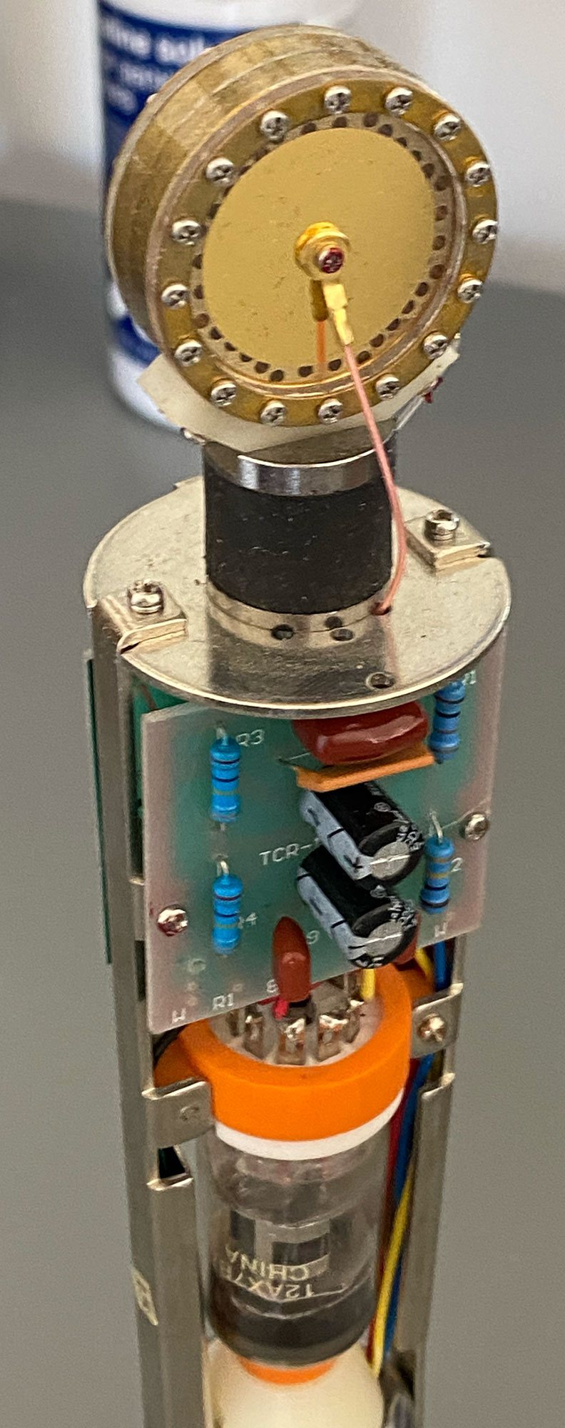 The circuit is built with inexpensive parts, as you might expect from anything made in China to meet a low price point. IMO, the circuit contains some design mistakes, which negatively impact performance, although perhaps not as much as the inconsistent component quality, haphazard build quality, and most importantly, inconsistent capsule voicing.
 Speaking of which, the capsule in all T11A mics is a 32mm K67. That’s a uniquely Chinese variation on the Neumann K67 design. The K67 capsule was designed to be used with high-frequency corrective EQ in the circuit. The T11A circuit does not provide any such filtering, so these mics often sound bright, especially when the low end is thin due to capsule manufacturing defects.
Acoustic analysis of the customer mic pair
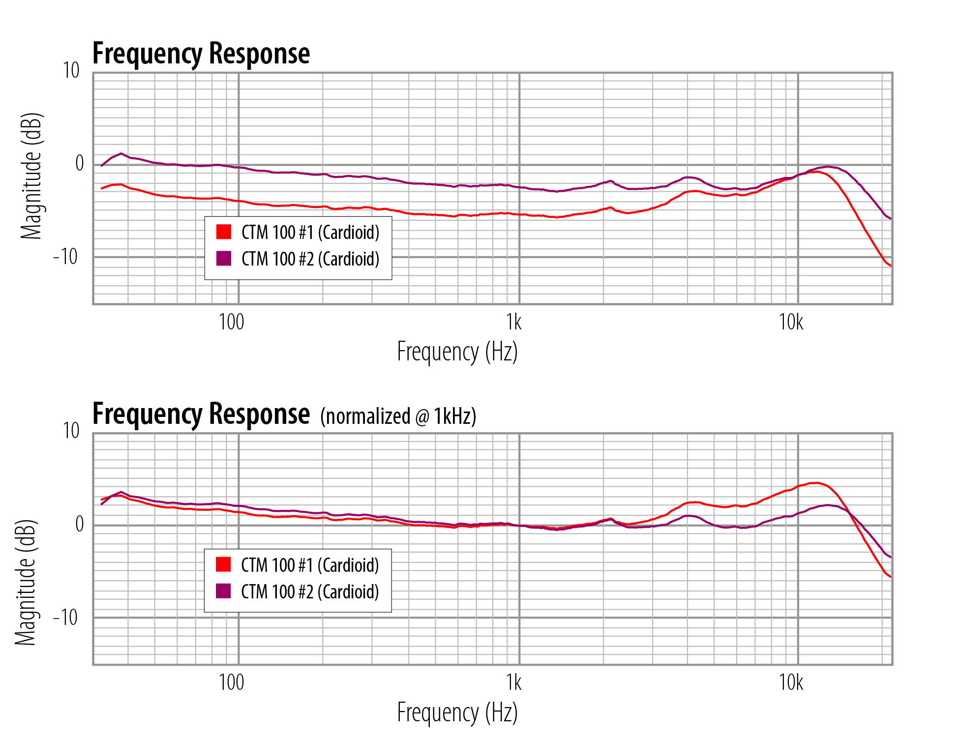
We measured both stock microphones on our acoustic sweep rig. We use a gated impulse system to reduce the influence of reflections. We measure at 10 inches (mic to speaker), so these graphs show proximity effect for directional microphones.
The image at right contains two versions of the Cardioid frequency sweep. The top one shows that the two mics differ in sensitivity (measured at 1kHz) by 3dB. The bottom graph (click the thumbnail to see it) normalizes both traces to 0dB @ 1kHz, to make it easier to compare the frequency response after accounting for the delta in level.
Mic #1 has a HF peak at +4.6dB @ 11.7kHz. Mic #2 peaks at +2.2dB @ 12.8kHz. That’s a 2.4dB delta in high-frequency response, and the peaks are 1100 Hz apart.
10-12kHz is a frequency band where a little goes a long way. Peaks in that band that are greater than about +1dB need to be accompanied by a boost in the lows, or else the mic will sound bright. These mics don’t have a full bottom end, though; at our 10-inch measurement distance, we like to see a more pronounced lift below 100 Hz. The lack of low end energy contributes to the thin and bright sound.
Not a matched pair
Could these two mics, in their current form, be used for stereo recording? Sure. Any two microphones could be used to record in stereo. In the case of these two mics, you would need to adjust preamp gain to compensate for the 3dB delta in output level. You would need to EQ both tracks individually. And if the source contains much energy above 10kHz, both these mics risk pushing the converter into harsh distortion because the mic is exaggerating that frequency band.
Performance as a stereo pair would be compromised by the sonic differences between the microphones. Digital EQ can’t completely adjust the brighter mic to make it sound like the less-bright one. Therefore stereo imaging would be affected. Making great stereo recordings is much easier if the mics sound the same.
Circuit analysis of the customer mic pair
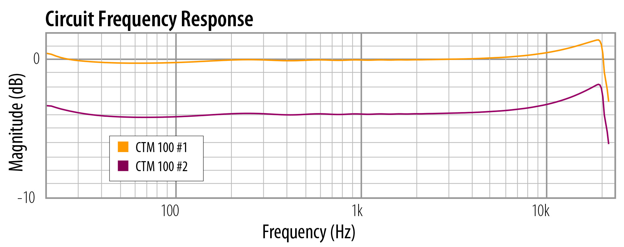 We tested the frequency response and distortion of the stock Carvin circuits by injecting a signal into the microphone. To be clear, this is not an acoustic test, but strictly an electronic test. This test bypasses the capsule, so that we can isolate the circuit (including tube and transformer) and graph its contribution to the sound of the mic.
The two Carvin circuits differed substantially in output level, by 4dB. That’s unusually high. With good-quality parts, this circuit should be within 1dB across multiple mics. This largeg delta suggests that one of these circuits has some incorrect or defective components.
The circuit frequency responses differed slightly, too. The higher-output mic had a 1.5dB lift from 5kHz to 18kHz. The lower-output mic had a 2.2dB lift in that region.
How much of a HF rise is appropriate for this mic circuit? I would say “none.” Some mic designers might want to boost the top end to compensate for a dark capsule, but that’s fairly unusual, and unlikely to explain what these graphs show. (And it’s worth recalling that the capsule used in these mics is arguably too bright already.)
Note the subtle oscillation in the response below 1kHz, too. That’s probably not audible, but indicates a problem in the circuit.
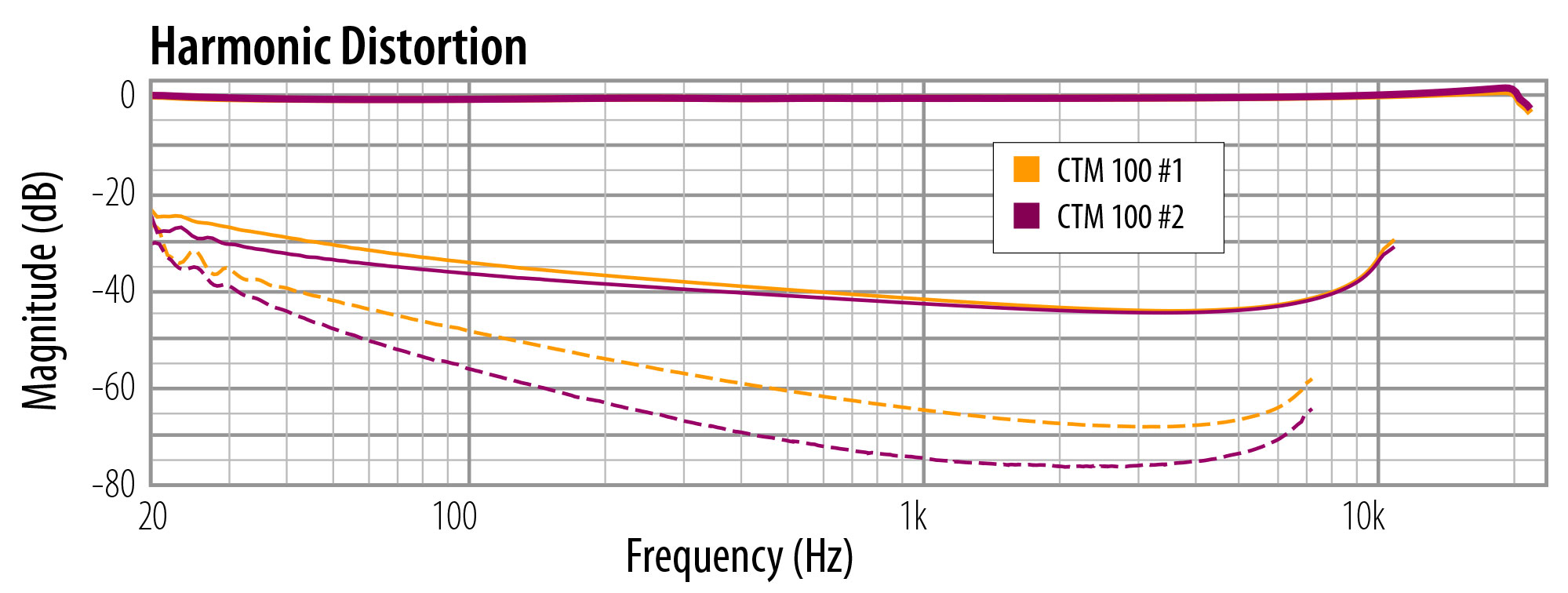 Now let’s look at distortion. In this graph, the heavy solid lines at the top show the circuit frequency response, which we’ve already seen. We’ve normalized both to 1kHz @ 0dB for this analysis.
The thinner solid lines show second harmonic distortion, which I’ll abbreviate as “2H.” This is one of the components of “tube mic sound.”
(Technically speaking, distortion is a defect, but let’s not pretend that the art of audio recording is about strictly and clinically capturing the sound in the room. Distortion is a musically useful effect. Ask any guitarist. It helps a source cut through the mix. It adds weight and mojo to a track. It’s not good or bad in itself, any more than the color blue is good or bad. What’s more important is when you use it, and how much, and what kind, and to what end.)
The dashed line is third harmonic distortion. Unlike 2H, 3H isn’t usually a desirable sonic seasoning. 2H is one octave above the source, and as such is always in key. 3H is three times the frequency of the source, which might or might not be in key, but is definitely not guaranteed to be, which means that instead of enhancing the source with saturation, it could potentially clash with the source by being off-key.
There is no rule about how much 2H is too much, but it is generally accepted that minimizing 3H is a good thing.
In the case of these Carvin mics, both 2H and 3H are higher than makes me comfortable; at moderate to high SPL, I would expect both of these mics to sound a bit rough.
Upgrade Options
Just to summarize what we’ve found: the capsules differ in frequency response. Both are thin on the bottom and hyped on top. The circuits differ in output level. Both exhibit an unwanted HF rise above 5kHz. Both have high distortion.
Replacing the capsules would re-voice both mics, but even if we installed matched capsules, the two microphones would not be matched because these circuits have a 4dB delta in output level.
Replacing both transformers might correct the output level difference, and might improve the distortion performance, but the only way to know is to do the replacement and then test both circuits via injection — which is to say, a lot of work, and a risk that the circuit problems were elsewhere.
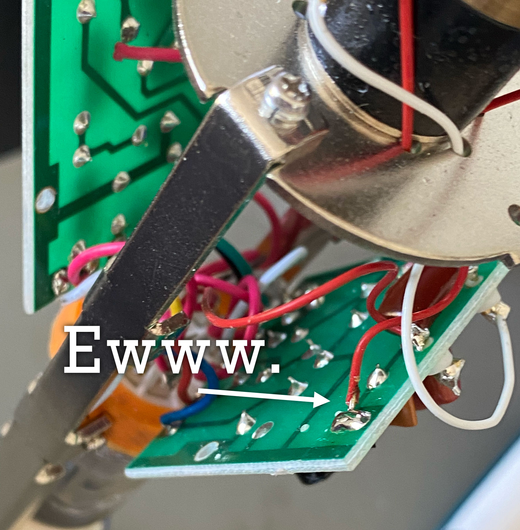
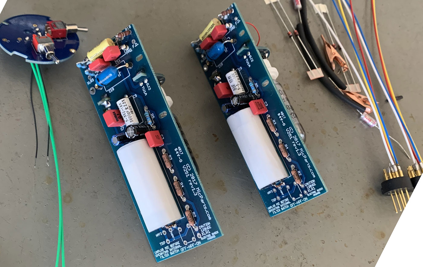
Ditto for the tubes. Furthermore, even if the tubes or transformers were responsible for the mismatched levels and high distortion, this circuit — in my opinion — contains some other compromises that negatively affect performance. Component quality is poor. The is no room for an upgraded output capacitor. Some of the existing wire joints are burned.
We always planned to replace the entire circuit, because that’s what the customer requested. I included these comments about partial-upgrade options only to illustrate the tradeoffs.
When both the capsule and the circuit are compromised, the only way to fix the mic is to replace both.
The V-251 Circuit Upgrade
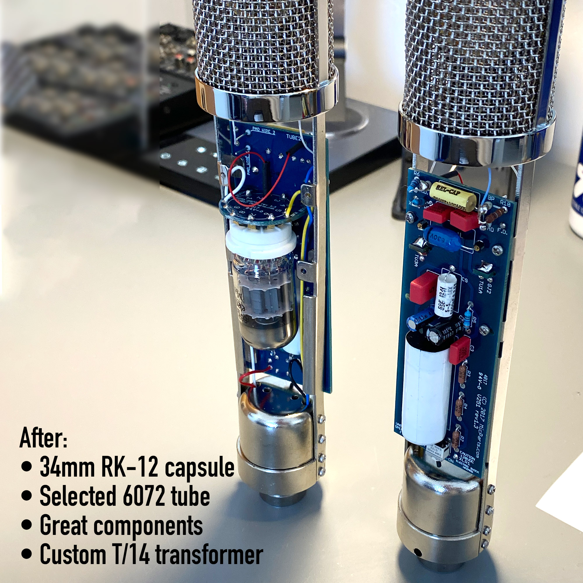
 We installed the V-251 circuit into both mics. The V-251 is our version of the Telefunken ElaM 251 circuit design. Like the original 251, this circuit uses one triode of a 6072 tube, a fairly minimalistic audio circuit, and a T/14 output transformer.
The tube in this kit is selected for low noise and low microphonics. The circuit components are all very high-quality, e.g. precision audio resistors, our favorite electrolytic capacitor on the tube cathode, and a truly amazing copper foil output capacitor.
 Because this circuit is most often used with the RK-12 capsule, which has a healthy bass response, the kit includes a high-pass filter feature. If the donor mic has external switches for pad and filter, the V-251 circuit accommodates those, but if the mic has no switches — as is the case here — the included internal HPF switch can be used. This allows the mic’s low frequency response to be attenuated when close-miking, to compensate for proximity.
We replaced all the internal wiring, too; the V-251 kit includes multistrand, Teflon insulated, silver plated copper wires.
Capsule Upgrade
The customer requested matched RK-12 capsules. This capsule is based on the AKG CK-12, an edge-terminated design that was used in the C12 and ElaM 251.
Results
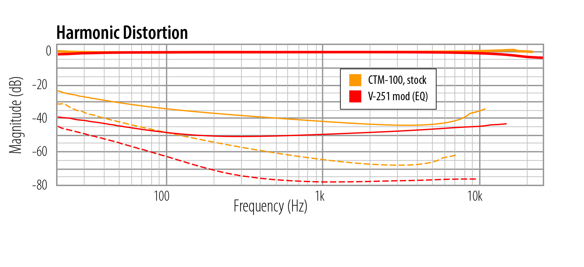 The image at right shows signal-injection tests of the stock circuit vs the V-251 circuit. Low frequency 2H dropped by 13dB. 3H dropped by 10-15dB across the spectrum. Both of those are solid sonic improvements.
The two circuits differ by less than 0.2dB in output level. We did not take any steps to match the circuits. The parts in these kits offer consistent performance, so any two circuits are likely to be matched for both level and distortion.
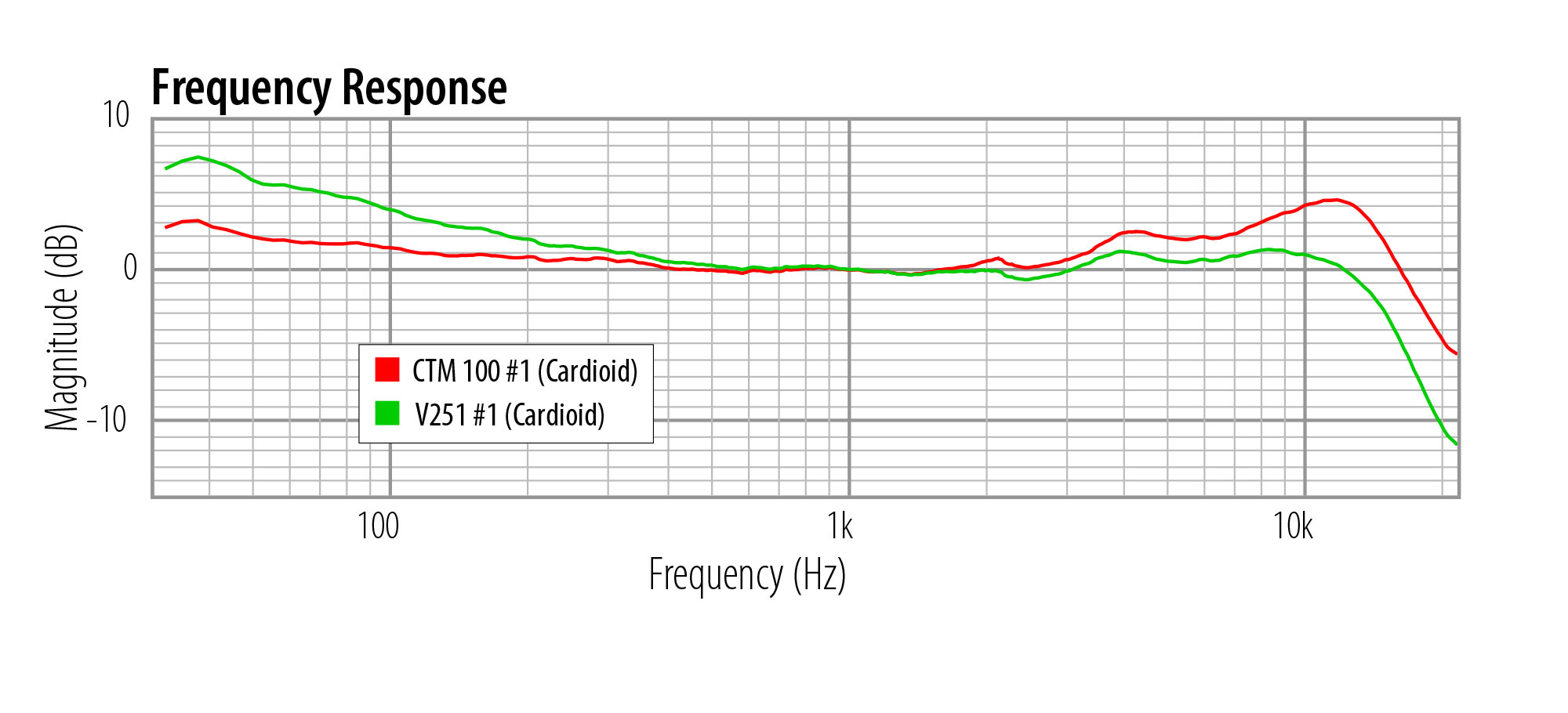 The acoustic frequency sweep is even more compelling. In this graph, the red trace is the stock Carvin mic. Compare the bass response: the modified mic has a much fuller low end, which is appropriate for this 10-inch measurement distance. The high-frequency peak moved down from +4.6dB (!) to a much more sane +1.1dB.
The mic now sounds balanced and rich, with great bass extension and plenty of “air,” with no 10-12kHz harshness. The improved bass response allows positioning farther from the source without sounding thin. The internal HPF switch allows closer placements without bass overload.
Harmonic distortion is reduced, giving the mic more headroom. There is enough 2H to give the mic character, but not so much that it becomes an “effect mic.”
The modified mics will go head to head with just about anything else. Its performance is not held back by any of its components. It has no funky circuit topology errors. It’s a really nice example of an ElaM 251 style microphone, albeit with 9 polar patterns and a switchable HPF (features not found on the original).
Is it worth it?
Building a mic locker on a budget is challenging, because you need a lot of them, and they’re all expensive.
That’s why upgrading inexpensive microphones is one of the best ways to create a collection of nice mics. Most commercial products can’t come anywhere close to the price/performance ratio of DIY upgrades.
Not every cheap mic is worth upgrading, of course. But mics like this one, where the entire signal path gets replaced, have no ceiling, no throttle on potential performance.
The most useful comparison is to figure out what a comparable-quality commerial mic would cost, if you bought it new. The recipe for this mic is a single-stage (single triode) 6072 with fantastic components, a T/14 transformer, and a CK-12 style capsule… a combination sometimes described as the “Austrian” sound. Such a mic would cost you $1900-$2400, which is more than FOUR TIMES the DIY parts cost. Add in the cost of the donor mic ($200 used), and you’re still saving over $1200 to go the DIY route. (And just between you and me, the components in the V-251 kit are actually nicer than what I’ve seen in any commercial mics.)
Related posts:

Posted in DIY, Microphones | No Comments »